British Explosive Ordnance
High Explosive Rockets Part 2
3-in Aircraft Rocket (Service)

H.E. 60lb F.
Overall length: 22 inches
Diameter: 4.5 inches
Total weight: 46.9 pounds
Overall length: 22 inches
Diameter: 4.5 inches
Total weight: 46.9 pounds
Fuzes used: No.899 Mk I
Filling: TNT or RDX/TNT 60/40
Filling weight: 3.9 pounds
25lb A.P. and S.A.P. Mk I
Overall length: 12.4 inches
Diameter: 3.44 inches
Total weight: 25 pounds

60lb S.A.P.
Overall length: 21.8 inches
Diameter: 6 inches
Total weight: 60 pounds
Fuzes used: No.865 Mk I, or No.878 Mk I
Filling: TNT or Amatol 60/40
Filling weight: 12 pounds
25lb S.A.P. Mk II
Overall length: 14.7 inches
Diameter: 3.8 inches
Total weight: 24.75 pounds
Filling: TNT or Amatol 60/40
Filling weight: 12 pounds
25lb S.A.P. Mk II
Overall length: 14.7 inches
Diameter: 3.8 inches
Total weight: 24.75 pounds

Rocket Motor:
Overall length: 55.19 inches
Diameter: 3.25 inches
Width of fins: 5 inches
Total weight: 35.1 pounds
Burning time at 60 degrees Fahrenheit: 1.5 seconds
Propellant:
-Mk I: Tubular Cordite
-Mks II and III: Cruciform Cordite
Propellant weight:
-Mk I: 12.6 pounds
-Mks II and III: 11.3 pounds
Overall length: 55.19 inches
Diameter: 3.25 inches
Width of fins: 5 inches
Total weight: 35.1 pounds
Burning time at 60 degrees Fahrenheit: 1.5 seconds
Propellant:
-Mk I: Tubular Cordite
-Mks II and III: Cruciform Cordite
Propellant weight:
-Mk I: 12.6 pounds
-Mks II and III: 11.3 pounds
General: This is an aircraft rocket weapon, designed primarily for use against submarines and merchant shipping, although more recently wide use of the rocket has been made against land targets of an unarmoured or lightly armored nature. The round consists of a 3-inch aircraft rocket motor and one of the five following heads: Shell, H.E., 60lb, F., No.1 Mk I; Shell, H.E., 60lb, S.A.P., No.1 Mk I (with delay); Shell, H.E., 60lb, S.A.P., No.2 Mk I (without delay); Shot, 25lb, S.A.P., Mk I; Shot, 25lb, A.P., Mk I; and Shot, 25lb, A.P., Mk II. In addition, two concrete practice heads are also used, one weighing 25lb, the other 60lb.
Description
Shell, H.E., 60lb, F., No.1 Mk I: This shell has been manufactured by modifying a 4.5-inch Howitzer shell. The nose of the shell is recessed and internally threaded to receive the nose fuze, while the base portion carries a threaded spigot for attachment to the shell ring of the rocket motor. The shell is painted dark green overall, with the designation stencilled in 1/2-inch yellow letters around the shell body.
Shell, H.E., 60lb, S.A.P., Nos. 1 and 2 Mk I: This shell consists of a cylindrical steel body internally threaded to receive a heavy steel ogival nose cap. The after portion of the body is internally threaded to receive a spigot, by which the shell is attached to the shell ring of the rocket motor. In the spigot are carried a gunpowder thermal initiator and a bsae fuze, beneath which is located a C.E. booster pellet. The shell is painted dark green overall, with a 1/2-inch white and a 1/2-inch red band near the nose. A 1-inch light green band is painted around the shell body, and on this band are stencilled the initials of the explosive main filling.
The Head No.1 Mk I employs the Fuze No.865 Mk I (with delay) and the No.2 Mk I uses the Fuze No.878 Mk I (without delay). This is the only difference in the two shells.

Shot, 25lb, S.A.P., Mk I: This is a solid steel shot. The nose portion of the shot is ogival, while the after portion terminates in a threaded spigot of reduced diameter, which screws into the shell ring of the rocket motor. The shot is painted black overall, except for the nose end, which is painted white for a distance of one inch.
Shot, 25lb, A.P., Mk I: Externally this shot appears identical to the S.A.P. shot. The nose portion is ogival, and the after body consists of a threaded spigot of reduced diameter, which screws into the shell ring of the motor. This spigot, in the case of the A.P. shot, is a separate component screwing into the internally threaded base portion of the shot. The spigot is held in place by a locking pin or a set-screw, which pierces the spigot and engages the shell body. The shot is painted black overall, but carries a 1/2-inch white band in addition to the 1-inch white tip on the nose.
Shot, 25lb, A.P., Mk II: This shot consists of a solid steel body machined externally to form a double ogive. This contour is considered to result in greater penetration and better underwater ballistics. Penetration is also enhanced by heat-treating the body of the shot. The after end of the body is recessed to form an empty cavity, and the base of this cavity is closed by a threaded spigot which screws into the shell ring of the rocket motor. The shot is painted black overall, with a 1-inch white tip and a 1/2-inch white band on the nose.
Shot, 60lb, Practice (Concrete), Mk I: This is a blunt-nosed cylindrical head consisting of an adapter, externally threaded to screw into the shell ring of the motor and fitted with eight steel reinforcing rods, welded into place. The concrete is then formed around the reinforcing rods and shaped to measure 20 inches overall and 6 inches in diameter.
Shot, 25lb, Practice (Concrete), Mk I: This shell is manufactured in an identical manner to the 60lb Practice Shell, but measure only 11.5 inches in length and 5 inches in diameter.
Motor, Rocket, A/C, 3-inch, No.1 Mk I: This motor consists of a long steel cylinder with a shell ring at the forward end held in place by eight locking pins, which are held in engagement by two circular band springs. A thin metal-headed obturator is located beneath shell ring and is separated by cardboard washers from the forward end of the propellant grain. The head of the grain is castellated to accommodate the Igniter, Fuze, Electric, No.53*. The base of the propellant grain is supported by a metal grid, which in turn rests against the tail obturator. The steel venturi tube is welded to the inside of the motor just behind the tail obturator and contains a bag of silica gel as a moisture-proofing measure.
The igniter leads extends from the igniter through the central annulus of the tubular cordite grain, along the outside groove of the cruciform grain in the Motors No.12 Mks II and III, through the tail obturator and venturi, and through the metal closing plate, and terminates in a two-pronged plug. This plug connects with a socket extension on the rail launcher, when the rocket is loaded aboard the plane.
Eight slots are located in the motor body near the after end for attachment of the four fins. The rockets are suspended by two saddles, each carrying a T-lug, which rides in the grooves of the launcher rails.
Motor, Rocket, A/C, 3-inch, No.1 Mk II: This motor differs from the No.1 Mk I in that the propellant grain is cruciform in shape rather than tubular. The igniter leads are brought along the outside grooves of the grain, rather than through a central annulus, and a different type grid is employed. Proposed new nomenclature for the Motor No.1 Mk II is: Motor, Rocket, A/C, 3-inch, No.5 Mk I.
Motor, Rocket, A/C, 3-inch, No.1 Mk III: The main difference between the Motors Mk II and Mk III is that the Mk III has a weak link pigtail as against a niphon plug in the Mk II motor. The proposed new nomenclature for this motor is Motor, Rocket, A/C, 3-inch, No.5 Mk II.
Motor, Rocket, A/C, 3-inch, No.1 Mk IV: This motor differs from the No.1 Mk III in that a small metal clip is loosely inserted over the igniter leads between the niphon plug and the attachment to the metal closing disc. The Motor Mk IV also has a longer pigtail lead; this greater length of lead being required for the lower round when using the "tier carriage" scheme. The proposed new nomenclature for this motor is Motor, Rocket, A/C, 3-inch, No.5 Mk III.
Remarks: These motors are colored either green or white overall, with identification stencilling in yellow.
3-in Aircraft Rocket, Air-to-Air (Soon-in-Service)


H.E. Shell
Overall length: 9.29 inches
Diameter: 3.25 inches
Total weight: 7.6 pounds
Explosive: TNT
Explosive weight: 2.125 pounds
Fuzes used: No.720 Mk IV
Explosive weight: 2.125 pounds
Fuzes used: No.720 Mk IV
Rocket Motor
Overall length: 31 inches
Diameter: 3.25 inches
Width of fins: 0.75 inches
Total weight: 19 pounds (approx.)
Propellant: 7 grains of tubular cordite
Propellant weight: 4.2 pounds
Burning time: 0.3 seconds
Overall length: 31 inches
Diameter: 3.25 inches
Width of fins: 0.75 inches
Total weight: 19 pounds (approx.)
Propellant: 7 grains of tubular cordite
Propellant weight: 4.2 pounds
Burning time: 0.3 seconds
General: This rocket was designed for upward vertical firing from heavy bomber aircraft to disrupt attacking formations of enemy fighters. The rocket head is fitted with a self-destroying fuze so that misses will not fall on friendly aircraft or territory after expiration of the rocket motor. The round consists of a 3-inch light ogival Shell No.2 Mk I fitted with a Fuze No.720 Mk IV, and a Motor, Rocket, A/C, 3-inch, Mks I and II "Sunflower Seed".
Description
Shell, H.E., 3-inch, No.2 Mk I: This shell was originally designed for use with the 3-inch anti-aircraft rocket and the Fuze No.701, but has been slightly modified for use with this rocket weapon. The shell consists of a light steel ogive struck with a 30-inch radius. The after part of the shell body is reduced in diameter and is threaded externally to screw into the shell ring of the rocket motor. An internally threaded fuze adapter is welded into the forward end of the shell body. A cardboard exploder container is inserted into the main explosive filling beneath the fuze adapter and contains two 12-dram CE booster pellets.
The shell is painted buff overall and carries a stencilled ring of red crosses 1/2-inch wide and one inch below the forward end of the shell body. A green band, upon which are stencilled the black letters TNT, is located 4.5-inch below the forward end of the shell. Complete identification, filling, and manufacturing information is stencilled in black on the shell body between these two rings.
Motor, Rocket, A/C, 3-inch, Mks I and II "Sunflower Seed": The rocket motor is a standard 3-inch proof motor reduced in length to 31 inches by elimination of a cardboard spacer sleeve. The motor consists of a cylindrical steel body, fitted at the head end with a shell ring, which is held in place by eight spring-locked pins. A head obturator is located behind the shell ring. The propellant consists of seven tubular grains of flashless cordite, each grain measuring 1 inch in diameter by 18 inches in length. The igniter leads pass from the igniter along the outside of the grains and end in a two-pronged niphon plug. A tail obturator is located aft of the propellant grains, and a venturi is located in the base of the motor. A small bag of silica gel is placed in the venturi as a moisture-proofing measure.
5-in Assault Rocket, "Sea Mattress" (Service)


H.E. Shell
Overall length: 11.6 inches
Diameter: 5 inches
Total weight: 29 pounds
Filling: Amatol (60/40 or 50/50) or Amatol and TNT
Fuzing: No.722 Mk III
Chemical Shell - Smoke Mk I/L
Overall length: 19.7 inches
Diameter: 5 inches
Total weight: 29 pounds

Overall length: 11.6 inches
Diameter: 5 inches
Total weight: 29 pounds
Filling: Amatol (60/40 or 50/50) or Amatol and TNT
Fuzing: No.722 Mk III
Chemical Shell - Smoke Mk I/L
Overall length: 19.7 inches
Diameter: 5 inches
Total weight: 29 pounds
Filling: CSA, FM, or WP
Fuzing: No.721 Mks I-III
Chemical Shell - Incendiary Mk I/L
Overall length: 19.7 inches
Diameter: 5 inches
Total weight: 29 pounds
Fuzing: No.721 Mks I-III
Chemical Shell - Incendiary Mk I/L
Overall length: 19.7 inches
Diameter: 5 inches
Total weight: 29 pounds
Filling: Perspex Benzole Gel
Fuzing: No.721 Mks I-III
Fuzing: No.721 Mks I-III

Rocket Motor
Overall length: 25.75 inches
Diameter: 5 inches
Width of fins: 1.9 inches
Total weight: 29 pounds
Propellant: 11 grains of tubular cordite
Propellant weight: 5.5 pounds (approx.)
Burning time at 60 degrees Fahrenheit: 0.35 seconds
Overall length: 25.75 inches
Diameter: 5 inches
Width of fins: 1.9 inches
Total weight: 29 pounds
Propellant: 11 grains of tubular cordite
Propellant weight: 5.5 pounds (approx.)
Burning time at 60 degrees Fahrenheit: 0.35 seconds
General: These rockets are intended primarily for beach barrage from landing craft. The incendiary bomb is employed only for ranging purposes, providing a visual indication of the attainment of the proper range. A change-over is then made to H.E., or smoke. The complete round consists of H.E. Bomb, and Propelling Tail, Rocket, 5-inch, No.1 Mk VI/N; Incendiary Bomb, and Propelling Tail, Rocket, 5-inch, No.1 Mk VI/N; or Smoke Bomb, and Propelling Tail, U. 5-inch, Mk III/N.
Description
Bomb, H.E., 29-lb, Mk I/L: This shell consist of a thin-walled steel forging, closed at the after end by an externally threaded base plate. The base plate carries a threaded spigot which screws into the shell adapter of the rocket motor. Set into the explosive filling at the nose end of the shell is an exploder container with two perforated and one solid C.E. booster pellets. The shell may be alternatively filled with Amatol or an upper layer of TNT and a lower layer of Amatol. If the former filling is employed, a TNT surround is located around the exploder container. The shell is painted buff overall.
Bombs, Smoke, and Incendiary, 5-inch, Mk I/L: These shells are of identical construction, differing only in the nature of the filling. The shell body consists of a metal cylinder welded to a closing plate at the nose end and to a tail plate at the rear. The closing plate is internally threaded to receive the fuze adapter, and a spigot is welded into the central opening in the base plate. This spigot is externally threaded to screw into the rocket motor and threaded internally to receive a tapered filling plug. For better ballistic qualities, a sheet steel nose fairing is fitted over the nose fuze, which protrudes through a central opening in the fairing. The fairing is held in place by a metal circlip around the outside of the fuze body.
Tail, Propelling, Rocket, 5-inch, No.1 Mk IV/N: This motor consists of a cylindrical steel body, the forward end of which is closed by a cast-iron pressure plate and a transit plug. Within the after end is a cast-iron venturi tube, closed by a closure plate to which are attached the automatic contact leads. A drum and four fins are attached to the after end of the motor for stabilization.
Ignition of the cordite propellant is achieved by a magnesium igniter fitted at the forward end of the cordite grains. The igniter is fired by an electric squib, Fuze, Electric, No. F. 53 Mk I, whose leads pass to two sockets fitted to, but insulated from, the venturi closing plate. An automatic contact disc connects one of the igniter leads to the "ground", in this case the motor body. The central brass disc of the automatic contact disc makes contact with an insulated spring finger on the projector.
These rocket motors must not be fired outside of the temperature range of 0 to 120 degrees Fahrenheit. Moisture-proofing is effected by a silica gel capsule fitted into the after end of the venturi tube.
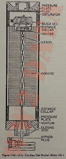
5-in Cordtex Net Rocket (Service)

Rocket Motor
Overall length: 18.25 inches
Maximum body diameter: 4.75 inches
Propellant: Tubular cordite
Maximum body diameter: 4.75 inches
Propellant: Tubular cordite
General: This motor was originally used to tow a specially constructed net of Cordtex (Primacord), used for demolition purposes. The net itself has been declared obsolete and is not in service use. The motor, however, remains a service item and may be used in the future for other purposes. The motor was originally called Motor, Rocket, 5-inch, Cordtex Net, Mk I. Proposed new nomenclature for the motor is Motor, Rocket, 5-inch, No.3 Mk I.
Description: The motor consist of a steel cylinder, threaded at each end to receive a pressure plate. The pressure plates are threaded internally, the forward one to receive a pressure plate plug and obturator, the after plate to receive the venturi. Two distance collars are beneath the pressure plates to position the cordite propellant grain, which is catellated at the forward end to receive the igniter.
The igniter consists of an electric squib, Fuze, Electric, No. F. 53, surrounded by a magnesium charge enclosed in a cartridge. The igniter leads pass through the central annulus of the cordite grain and through the venturi and closing disc, and end in a two-pronged niphon plug. During shipment and storage, the niphon plug and igniter leads are protected by a tail closing cup, which is fastened to the motor body by adhesive tape.
As a moisture-proofing measure, a bag of silica gel is fitted in the forward end of the motor cylinder.
Anti-Submarine Rocket Assembly


Depth Charge
Overall length: 37 inches
Diameter: 11 inches
Total weight: 260 pounds
Explosive: Amatol
Explosive weight: 180 pounds
Fuzing: Depth Charge Pistols Mk XIV or XVI

Overall length: 37 inches
Diameter: 11 inches
Total weight: 260 pounds
Explosive: Amatol
Explosive weight: 180 pounds
Fuzing: Depth Charge Pistols Mk XIV or XVI

Rocket Motor
Overall length: 20.25 inches
Diameter: 2.25 inches
Total weight: 6 pounds
Propellant: Cogged cordite (SU/K/C029)
Propellant weight: 1.3 pounds
Burning time at 60 degrees Fahrenheit: 0.45 seconds
Overall length: 20.25 inches
Diameter: 2.25 inches
Total weight: 6 pounds
Propellant: Cogged cordite (SU/K/C029)
Propellant weight: 1.3 pounds
Burning time at 60 degrees Fahrenheit: 0.45 seconds
General: This ammunition is designed for harbor defense purposes and will probably not be used afloat.
Description: The round consists of one Depth Charge Mk XI, without tail, fitted with 12 Propelling Tails, Rocket, No.5 Mk II. These motors are mounted in a cylindrical shell encircling the depth charge. The shell measures about 21 inches long by 17 inches external diameter, and weighs about 100 pounds. The complete round assembled weighs about 375 pounds.
The round is fired electrically from a single-mount, trough-type launcher. The electrical circuit is selectively arranged so that from 4 to 12 motors may be fired, giving ranges varying from 65 to 500 yards in 50-yard increments. Large fins may be fitted to the round, but at ranges under 300 yards, fins are usually omitted from the assembly.
Tail, Propelling, Rocket, No.5 Mk II: This motor consists of a cylindrical steel body with a shell ring fixed in the forward end by eight locking pins held in engagement by a circular band spring. A metal-cased igniter is located immediately behind the shell ring. An electric squib is inserted in the base of the igniter, the leads from the squib extending through the central annulus of the cogged cordite grain and the venturi, and ending in a two-pronged niphon plug. Behind the igniter, positioned by a metal support ring is located the cordite grain, which is supported at its after end by a metal grid. Separating the grid from the venturi is a thin metal tail obturator. The venturi is located in the after end of the motor body and contains a small bag of silica gel as a moisture-proofing measure.
Next Time: Rocket Flares, Wire-Barrage and Pyrotechnic Rockets
No comments:
Post a Comment